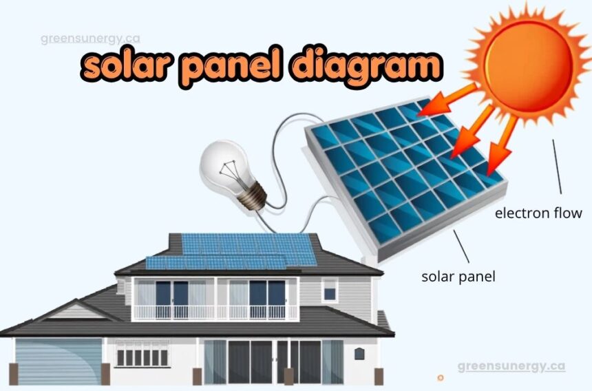
A clear solar panel diagram makes solar power easy to understand. I remember the first time I looked at a real solar panel diagram on a job site. Every wire and box suddenly made sense. This guide breaks the diagram down piece by piece. We keep the language simple. We keep every sentence short. Let’s start from the very top of the panel and work our way down to the wiring.
What Is a Solar Panel Diagram Exactly
This drawing shows how a solar system fits together. It uses electrical symbols to represent panels, wiring, and safety devices. Installers rely on these drawings to avoid wiring mistakes. Engineers use the same drawings to check system safety and calculate loads.
Most homeowners never see a real diagram before installation day. That is a missed chance to understand your own system. A good installer will walk you through the layout before work begins. This builds trust and avoids confusion later on. Reading a diagram does not require an engineering degree. Once you know the basic symbols, the whole picture becomes clear. Panels, boxes, and lines all follow a consistent pattern across most projects.
Different countries and states follow slightly different symbol standards. Still, the core logic stays the same everywhere. Power flows from the panels, through safety devices, and into your home or the grid. Once you spot that flow, every diagram starts to look familiar.
Why a Solar Panel Diagram Matters for Installation
Permit offices ask for a complete solar panel diagram before approving any project. Missing or unclear diagrams cause long delays. Some projects lose weeks waiting on corrected paperwork. A strong diagram set speeds up approval significantly. These drawings also protect the people doing the physical work. Field crews follow the diagram to route wires correctly. Skipping this step raises the risk of shock, fire, or equipment damage. A clear diagram keeps everyone on site safer.
Accurate diagrams also help long after installation finishes. Future electricians can service the system faster when the original wiring diagram is available. This saves money on troubleshooting for years to come. Insurance companies sometimes request these records too. A stored diagram proves the system met code at the time of install. Homeowners selling their property also benefit, since buyers often ask for proof of a compliant setup.
read more about: used solar panels
Key Parts Shown in a Solar Panel Diagram
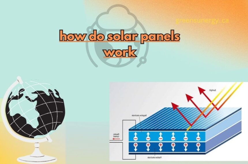
Every panel begins with photovoltaic cells that turn sunlight into electricity. A layer of tempered glass sits on top and protects those cells from weather and debris. Beneath the glass sits the encapsulant, a clear material that holds everything in place while blocking moisture. The backsheet forms the bottom layer of most panels. It adds insulation and shields the cells from the elements below. A metal frame wraps around the whole unit, usually built from aluminum for strength and light weight.
On the back of the panel sits the junction box. This small container holds the electrical connections and the bypass diode, which reroutes power around any shaded section. Together, these parts appear clearly labeled inside a proper electrical drawing. Cell technology also shapes what shows up on the drawing. Some panels use a single pure silicon crystal for higher efficiency. Others melt multiple crystals together for a lower cost option. Either way, the diagram labels the cell type so installers know exactly what they are working with.
Types of Solar Panel Diagram You Should Know
A single line diagram offers a simplified view of the whole electrical path. It shows how the array connects to the inverter, the disconnect switch, and the main service panel using one continuous line. A wiring diagram goes much deeper. It lists wire sizes, conductor colors, and conduit paths for the entire install. Field electricians depend on this drawing every single day on site.
A site plan shows the property from above. It marks the array location, the utility grid connection point, and any trenching needed for conduit. This drawing confirms the project meets local zoning rules.An array layout focuses purely on panel placement. It notes the azimuth, the tilt angle, and the row spacing between panels. Good spacing prevents shading between rows and boosts total output.
Roof mounted arrays face extra constraints compared to ground mount systems. Vents, chimneys, and skylights all create obstacles the layout must work around. A skilled designer studies these obstacles closely before finalizing panel positions, since even small shadows can lower output across an entire string.
read more about: prizmatem
How to Read a Solar Panel Diagram Like a Pro
Start by finding the array on the page. Follow the line from the panels toward the combiner box or string inverter. Each stop along that path represents a real physical component on your roof or ground mount. Next, look for the disconnect switch symbols. These allow crews to safely cut power during maintenance. Every safe diagram includes at least one clearly marked disconnect point.
Finally, check the grounding and bonding section. This part protects the whole system from electric shock and lightning strikes. A properly grounded system keeps your home and your family safe for decades.
Take note of any voltage ratings and wire gauges printed next to each symbol. These numbers confirm the system was sized correctly for its location. A mismatch between the printed rating and the installed part is a red flag worth raising with your installer right away.
Tools Used to Create a Solar Panel Diagram
Professional teams rarely draw these plans by hand anymore. Most rely on specialized software that builds each diagram to exact scale. This software pulls panel specifications, wire ratings, and code requirements straight from a shared database. Automated tools also reduce human error during the design stage. A small mistake in a hand drawn diagram can lead to a rejected permit weeks later.
Software catches many of these mistakes before submission, saving both time and money. Even with good software, a trained reviewer should still check every drawing. Local code differs from one jurisdiction to the next. A tool cannot always catch a rule that only applies in your specific city or county.
Common Questions Installers Hear About Diagrams
Homeowners often ask why permitting takes so long. The answer usually comes back to missing or incomplete drawings. A complete package including the shading analysis and monitoring diagram moves through review much faster.
Shading analysis predicts how nearby trees or buildings affect output across the year. Monitoring diagrams map the data path between the inverter, sensors, and your phone app. Both drawings support long term performance, not just installation day.
Final Thought
A well prepared solar panel diagram protects your investment for decades to come. It speeds up permitting, guides safe installation, and helps future technicians service your system with confidence. Take time to review your own solar panel diagram before signing off on any project. A few extra minutes spent reading the drawing can save real money and real stress later on.
FAQs
1. What Is Shown on a Solar Panel Diagram
A solar panel diagram shows panels, wiring, inverters, disconnect switches, and grounding paths. It gives installers and inspectors a full picture of the system before work begins.
2. Why Do Permit Offices Need a Diagram
Permit offices use the solar panel diagram to confirm the system follows safety code. A clear diagram prevents delays and reduces the chance of rejected applications.
3. Can I Read My Own Diagram
Yes, most homeowners can learn the basic symbols quickly. Ask your installer to walk through your diagram before installation starts.
4. Does Every Solar Project Need Multiple Diagrams
Most projects need several drawings, including a single line diagram, a wiring diagram, and a site plan. Larger systems may also require shading and monitoring diagrams for full approval. Commercial projects often need even more documentation than a typical home install, since inspectors review larger loads and more complex wiring paths.